

What Is The Best Fet To Use In Motor Controller
Using MOSFET Drivers for Motor Drives

Get valuable resources directly to your inbox - sent out in one case per month
We value your privacy
Introduction
In motor drive systems, a gate driver or "pre-driver" IC is often used forth with N-channel power MOSFETs to provide the high current needed to drive motors. There are a number of pattern considerations to be fabricated when selecting the driver IC, MOSFETs, and in some cases associated passive components. Often this procedure is poorly understood, and implementations are less than optimal.
This article will hash out unproblematic methods to select components for a pre-driver/power MOSFET excursion, and the resulting performance of the system.
Start with the Motor
To design a DC motor drive — whether information technology is for a brush motor or a three-phase brushless motor — the motor characteristics will decide the blueprint details of the drive. The two primary factors that help define the drive blueprint are the operating voltage and current requirements of the motor.
However, these parameters are not equally simple as they might beginning appear. Motors are usually given voltage and current ratings, merely in actual operation, the operating values may vary from these ratings. Motor speed is adamant by the voltage applied. The current needed by the motor depends on the torque applied to the motor. Therefore, the bulldoze may or may not need to be designed to the total specifications of the motor.
The speed constant and torque constant — usually given in a motor's datasheet — tin can be used to estimate the voltage and current needed in a item application. The drive must be powered from a voltage at least as high equally that required to get the desired speed from the motor, but the supply voltage is often determined by the voltage available to the organisation. The maximum current requirement is usually set by the torque needed to start up the motor with a mechanical load.
Choosing the MOSFETs
Be sure to cull ability MOSFETs that are rated for at to the lowest degree the power supply voltage and the maximum electric current needed past the motor. Some margin is necessary also.
By and large, the bleed-to-source voltage rating (VDS) of the MOSFETs should be at to the lowest degree 20% higher than the supply voltage. In some cases — especially in systems with large currents, large torque steps, and poorly controlled power supplies — this required margin may exist as much as twice the supply voltage.
The current rating of the MOSFET must of form be high enough to provide the peak electric current needed by the motor, but usually thermal considerations boss. The MOSFETs dissipate power and generate heat in the bleed-source resistance: RDS(ON). Thermal constraints, including the ambient temperature and any heatsinking available for the MOSFETs, set up limits on how much power tin can exist dissipated. This maximum allowable power dissipation drives the pick of the MOSFETs based on the RDS(ON) value.
Once the necessary voltage rating and RDS(ON) have been determined, it is important to consider the total gate charge (QThou). The gate charge is a measure of how much accuse is needed to plow the MOSFET on and off. A MOSFET with a lower QG is easier to bulldoze. Information technology can be switched faster, with a lower gate bulldoze current, than one with a high QThou.
Gate Drive Current and Rise/Fall Times
The gate of a power MOSFET tin be viewed as a nonlinear capacitance between the gate and source terminals. Fifty-fifty though the gate does non conduct DC current, current is needed to charge and discharge the gate capacitance to plough the MOSFET on and off. The amount of current provided to the gate determines how much time it takes to fully turn on the MOSFET. Similarly, when current is pulled out of the gate, that corporeality of current sets the MOSFET plough-off fourth dimension.
To empathize what is needed to drive the gate, one needs to know how fast the MOSFET must exist switched. In that location is a pattern tradeoff fabricated betwixt low switching losses (which require fast rising and fall times) and depression EMI (which requires slow rise and fall times). In add-on, the PWM frequency and minimum and maximum required duty cycles put a fourth dimension restriction on how fast switching needs to exist. For example, with a 20kHz PWM frequency, a ane% duty bicycle requires generating a pulse that is 500ns long. This requires a rise and fall time of a few hundred nanoseconds or less.
After determining what rise/autumn time is required, calculate the necessary gate drive current. This tin can exist estimated as QG / t, where QOne thousand is the total gate charge and t is the desired rise/fall time.
Annotation that this is the amount of current that would demand to be driven for the entire rise/fall time — in reality, the gate drive electric current unremarkably varies somewhat over this time, equally most gate drivers are not constant-current drivers.
If delivering a constant current into the gate, the voltage at the gate is not a linear gradient — it reaches a plateau during the fourth dimension that the MOSFET is switching (run into Figure 1). This is called the "Miller plateau," and is caused past the gate-bleed capacitance. When the drain is transitioning, this capacitance takes current to charge, so the charging of the gate-source capacitance slows.
The lower the electric current provided to charge the gate, the longer the time that it takes the transition to complete.
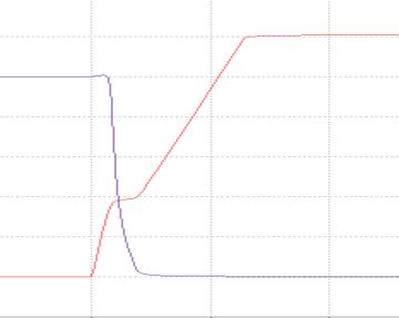
Effigy i: 1A Constant-Current Gate Drive (100nC - Red = gate, purple = drain, 200ns/div.)
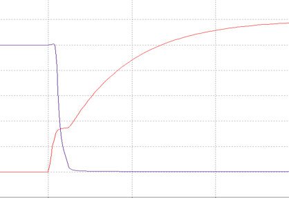
Figure ii: 12V Gate Bulldoze with 12Ω Series Resistance (100nC - Ruby-red = gate, purple = drain, 200ns/div.)
Figure 2 shows the waveforms if a 12V constant voltage gate bulldoze is used with 12Ω series resistance. The plateau is still there and information technology takes longer for the gate to reach 12V, but the switching time at the drain is most the aforementioned.
Selecting a Pre-Commuter IC
One time you know the minimum gate bulldoze electric current that will exist required, select a gate driver (pre-driver) IC that can support this current. There is a broad diverseness of these parts available, with dissimilar numbers of channels, gate drive current capabilities, and supply voltage ranges. Additional integrated features, such as current-sense amplifiers and protection circuits, are besides available in some parts.
Pre-driver ICs are bachelor from many semiconductor suppliers that make products for ability management, including MPS. There are a wide variety of single-channel and iii-channel pre-driver ICs designed for DC motor drives, including the three-channel 60V and 100V families, every bit well equally single-phase, 100V devices.
Some pre-driver ICs generate the required gate drive voltages internally from the principal motor power supply, using linear regulators, charge pumps, and/or bootstrap capacitors. Others require a carve up gate bulldoze power supply. To operate at 100% duty cycle (with output loftier for an extended period of time), choose a pre-driver with an internal charge pump to keep the high-side gate turned on for an extended period. Pre-drivers that rely only on a bootstrap for the high side tin can but keep the high-side MOSFET on for a limited fourth dimension, equally leakages bleed the bootstrap capacitor after some time.
The gate driver must be able to provide at to the lowest degree the corporeality of electric current needed to achieve the rise and autumn times needed described higher up, but a driver with more current capability can besides be used.
Some commuter ICs provide a way to adjust rise and fall times (also called "slew rate accommodate") by varying the amount of gate drive within the part. When using parts without a built-in slew rate aligning, the user can insert resistance betwixt the gate commuter output and the MOSFET gate. This limits the gate electric current, and slows the rise and fall times.
Get independent rise and fall times past calculation a diode (run into Figure iii).
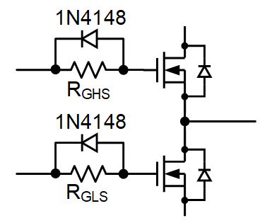
Figure three: Diagram for Adding a Diode
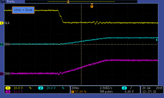
Effigy 4: Gate and Output Waveforms
This is often done to ensure that ane FET in a half-span arrangement turns off fully before the opposing FET turns on, which guarantees dead time. Figure 4 shows that the low-side gate (GLA) drops very chop-chop every bit information technology is discharged through the diode, but the high-side gate (GHA) charges slowly due to the resistor. The result is a deadening rise time at the output (SHA), controlled past the loftier-side MOSFET turn-on.
Since the gate has a nonlinear capacitance and the driver is usually not a true voltage or current source (typically it is a FET operating in a linear region), it can be difficult to accurately calculate the necessary resistance to reach a specific rise or fall fourth dimension. It is usually best to derive the correct values experimentally, or through simulation. Beginning with the assumption that the gate drive electric current will equal the gate drive voltage (often 12V) divided by the serial resistance, and piece of work from in that location. Be sure to as well include the output resistance of the gate commuter when making this adding.
Conclusion
This commodity provided some applied information to select the best components for use in a motor drive with a pre-driver IC and ability MOSFETs. Hopefully information technology will help you lot in selecting the right IC and associated components in your side by side motor bulldoze design.
_________________________
Did you observe this interesting? Become valuable resource straight to your inbox - sent out once per calendar month!
Technical Forum
Get technical support

What Is The Best Fet To Use In Motor Controller,
Source: https://www.monolithicpower.com/en/using-mosfet-drivers-for-motor-drives
Posted by: schnabelnumpat.blogspot.com
0 Response to "What Is The Best Fet To Use In Motor Controller"
Post a Comment